the Raspberry Pi device, beyond just being a low-cost introductory computing tool, also provides a robust electronic controller interface that enables programmatic control of external electronic systems. These systems can be as simple as turning on or off an LED, or as complex as being able to control a robotic arm or other, more elaborate, electronic devices. This Python and embedded programming tutorial will show the reader how to use Raspberry Pi-specific Python libraries to control basic electronic components. Many similar Python tutorials assume extensive knowledge in the use of such components, but this article will not make that assumption. Instead, programmers will be shown a “gentle” introduction into the electronics concepts needed to get this project going, in the hopes that this foundation will encourage the reader to do more experimentation beyond the simple experiment to be presented within this two part programming series.
This article, and the second part of it, presumes that the reader has a basic understanding of how to navigate the Raspberry Pi OS – namely, how to log in, open a terminal window, and how to use a text editor. It also presumes a basic understanding of the Python programming language and concepts.
Reading: CUPS and Raspberry Pi AirPrinting
How to Power External Devices with Raspberry Pi
Most Python programming tutorials present two approaches to powering external electronic devices with a Raspberry Pi. These are:
- Using the Pi itself to control and power such external electronics.
- Using the Pi only to control external electronics, with the power coming from a separate source.
While the first approach is much simpler, it is very limited in what it can demonstrate, and it does not make for a practical experiment. On top of this, the Pi is very limited in how much power it can send over its GPIO pins, and beyond the possibility of damaging the Pi via an electrical overload, there just aren’t that many devices that can run on this limited amount of power.
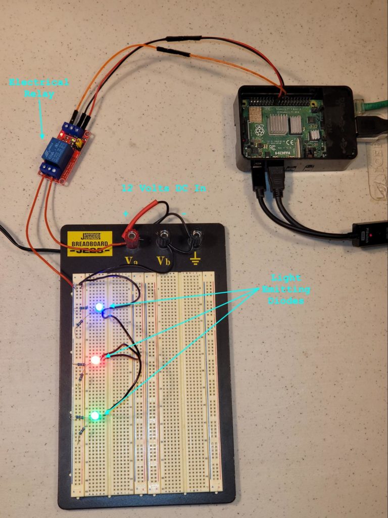
This embedded programming tutorial series will demonstrate the second approach. While it may present a steeper learning curve for a beginner, it is well worth learning about the kinds of cheap electronic devices that can allow for the Pi to control a wider array of devices. This demonstration will show how to build the basic circuit below:
Figure 1 – The Completed Demonstration Circuit
In this particular circuit, the 3 LEDs all activate when GPIO 25 (Pin 22 on the Raspberry Pi GPIO Header) is activated. Below is a closeup of the connections to the GPIO Header. Note the J8 label at the lower right. The pins of on the GPIO Header are always numbered starting from the J8 label, with even-numbered pins being closer to the edge of the Pi and odd-numbered pins being closer to the center of the Pi:
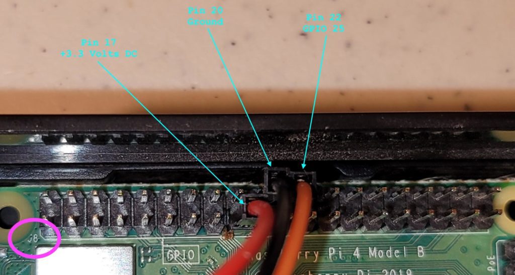
Figure 2 – Wiring Connections to the GPIO Header
Note, the name of the GPIO header, in this case, GPIO 25, does not correspond to the Pin Number on the Raspberry Pi Header!
The wires used to connect the Raspberry Pi to the Relay are from the “Chanzon 120pcs 10cm Header Jumper Wire Dupont Cable Line Connector Assorted Kit Set” which is available on Amazon.
Reading: Using a Raspberry PI Device as an OpenVPN Server
Electronic Components Crash Course for Embedded Programming
Below, we will discuss the different electronic components used in this tutorial and for embedded programming with the Raspberry Pi.
wiring
Circuits cannot exist without anything to connect the components. In the demonstrations in this tutorial, the wire used is from the “22 Gauge Wire Solid Core Hookup Wires – 22 AWG Pre-Tinned, PVC (OD: 1.5mm) Coated Copper Wires 6 Colors (Black, Red, Yellow, Green, Blue , White) 33ft or 10m Each, Hook Up Wire Kit from Plusivo” which is available on Amazon as well. Other tools which will be helpful are:
- Wire strippers
- wire cutters
- Digital multimeter
A quick, important note: do not use scissors to cut wiring – doing so will damage the scissors.
power supplies
The easiest way to get a power supply is to cannibalize an unused AC adapter from a no-longer-used piece of hardware. For the demonstration, an AC Adapter with an output of 12 Volts DC and a maximum current rating of 1.5 Amps worked perfectly. Make sure the AC Adapter is unplugged before cutting off the end, stripping the wires, and connecting them to the breadboard.
relays
The relays used in this demonstration are “5v Relay Board Relay Module 1 Channel Opto-Isolated High or Low Level Trigger” and are available on Amazon. They are connected as shown below:
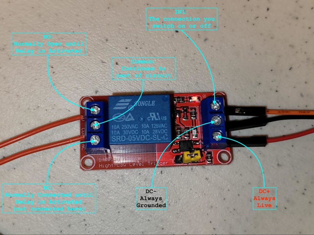
Figure 3 – Electrical Relay Connections
An Electrical Relay is essentially a voltage-controlled switch. The DC+ and DC- connections are what power the relay and there may be a LED on the relay that indicates that it is powered. A relay being powered is not the same as it being activated. In order to activate the relay, the voltage on the IN1 connector must be set to match the voltage on DC+. As long as the voltage on IN1 matches what is on DC+, the relay will remain activated. DC+ and IN1, when activated, will oppose the DC- connection. In order to deactivate the relay, set the voltage on IN1 to match DC-. There may be another LED on the relay that indicates that it is activated. Toggling between activating and deactivating the relay usually results in an audible “click” sound being heard.
When the relay is powered and activated, it will enable an electrical connection between the Common (COM) terminal and the “Normally Open” (NO) terminal. Simultaneously, it will disable the electrical connection between the Common terminal and the “Normally Connected” (NC) terminal. When the relay is deactivated, the connection between NO and COM will be disabled (also known as “open”) and the connection between NC and COM will be enabled (also known as “closed” or “shunted”).
Below is the relay without the connections, with the terminal labels more clearly visible:
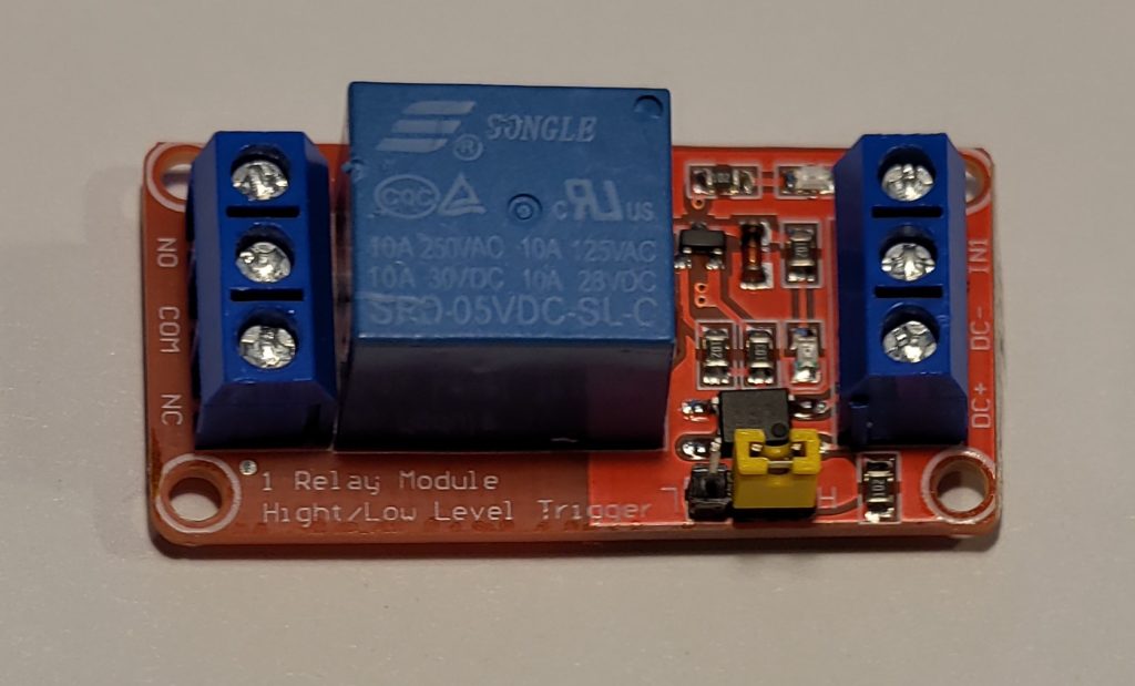
Figure 4 – The Relay without any connections
This particular relay includes a yellow jumper which can reverse the relay’s operation. In the photo above, the jumper is next to the letter “H” meaning that the relay will activate when IN1 matches DC+. If the jumper is set to the L position (the L is upside down in the photo above) then the relay will activate when IN1 matches DC-. One example of a use case for such a feature might be a sensor attached to a door that creates a closed circuit to IN1 when the door is closed. A relay configured to activate when IN1 matches DC- could be used to trigger an alarm when the door is opened, as a result of the circuit to IN1 becoming open.
Not every relay has this feature.
Danger warning: This demonstration uses low-voltage DC power and it should not pose a shock or electrocution hazard, but if you are in any way sensitive to such currents, do not attempt this demonstration. Do not exceed the electrical limitations of the relay or other electronic components! If you are working with anything close to 120 VAC or higher voltage electricity, ensure that all proper electrical safeguards are in place! Consult an electrician if you are not sure! Always make sure the power is turned off to any electronic devices and your Raspberry Pi before connecting or disconnecting any wires. You may be seriously injured or killed if you ignore these warnings.
Light emitting diodes
A diode allows current to flow only in one direction. A light emitting diode is a special case of diode which lights up only if the current is flowing in the proper direction. All LEDs have two legs of uneven length, with the longer one being the positive connection (anode) and the shorter one being the negative connection (cathode):
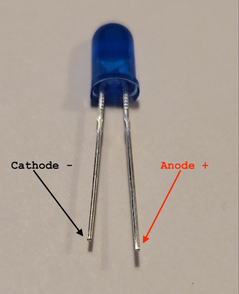
Figure 5 – LED with connections explained
LEDs have a hard and fast voltage range. The ones used in this example are able to take an input voltage of 2.0 to 3.2 Volts DC. The LEDs used for this demonstration are “DiCUNO 450pcs (5 Colors x 90pcs) 5mm LED Light Emitting Diode Round Assorted Color White/Red/Yellow/Green/Blue Kit Box” and are available at Amazon. Note, connecting an LED backwards or using too high of a voltage can damage the LED.
resistors
Resistors intentionally impede the flow of electricity. They can be used to lower the voltage of what might otherwise be an unsuitably high input voltage into something that the electronic components are able to consume. Note that, at the beginning of this article, the first diagram showed a 12 Volts DC power supply being used. This is clearly too high of a voltage for the LEDs presented above. Using a bit of Electrical Engineering “witchcraft,” the proper circuit to convert the voltage is shown below:
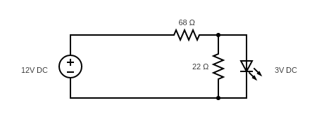
Figure 6 – Using Resistors to lower the LED input voltage
The diagram above was drawn using the “Circuit Diagram Web Editor” at https://www.circuit-diagram.org/editor/. Below is a closeup of the implementation. The layout may vary depending on the breadboard used. The resistors are “AUKENIEN 1/4W Resistor Assortment Kit 40 Values 400pcs 1/4 Watt Metal Film Fixed Resistors Variety Pack 0 Ohm to 10M Ohm 1/4Watt 0.25 watt Common Resistors Assorted RoHS Compliant with ±1% Tolerance” and are available at Amazon.
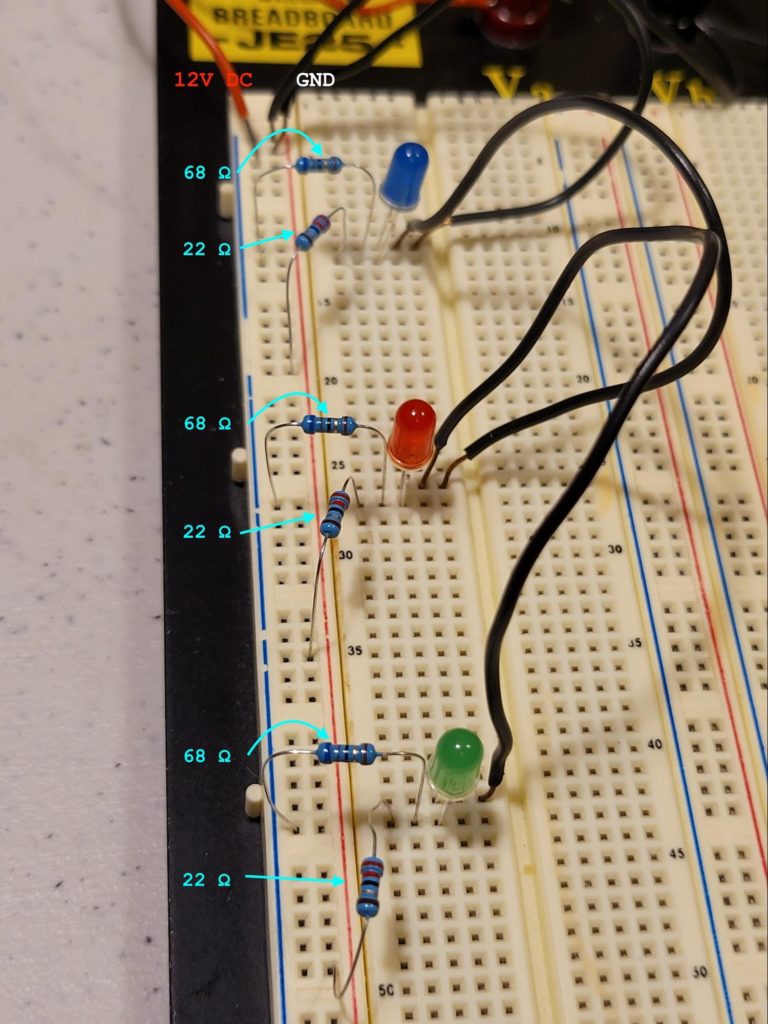
Figure 7 – Closeup of the implementation
The implementation can be tested without writing any code by connecting the wire going into the NO terminal on the relay into the NC terminal instead. If the wiring is correct, then all 3 LEDs should light.
Momentary switches
A momentary switch can consist of a rocker or a push button. In its default state, such a switch usually keeps the circuit open. Pressing and holding down the rocker or the push button completes the circuit. Releasing the button or rocker reopens the circuit.
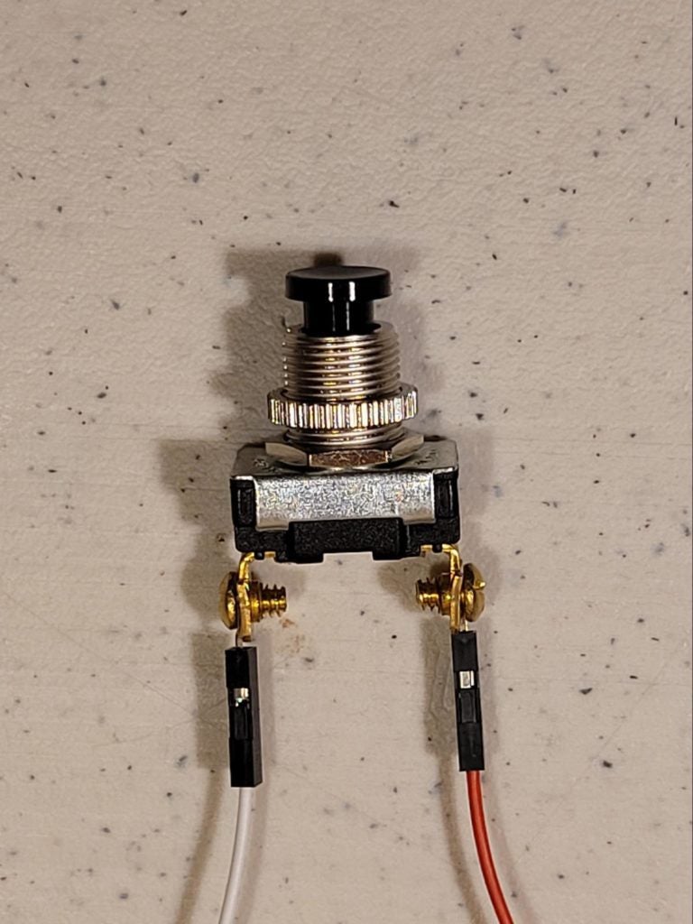
Figure 8 – A Momentary Switch
In most wiring diagrams, electrical switches have a line, which comes from the power source, and a load, which connects to the device that is to be switched on or off. The switch above is a single pole, single throw switch so either terminal can serve as the line or the load. This particular switch is a “Gardner Bender GSW-22 Electrical Push Button Switch, SPST, OFF-Mom ON, 6 A/120V AC, Screw Terminal , Black” and it is available from Amazon.
The GPIO header
Each of the pins on the GPIO Header has a specific name and purpose. To see the pinout, simply execute the pinout command in the terminal window:
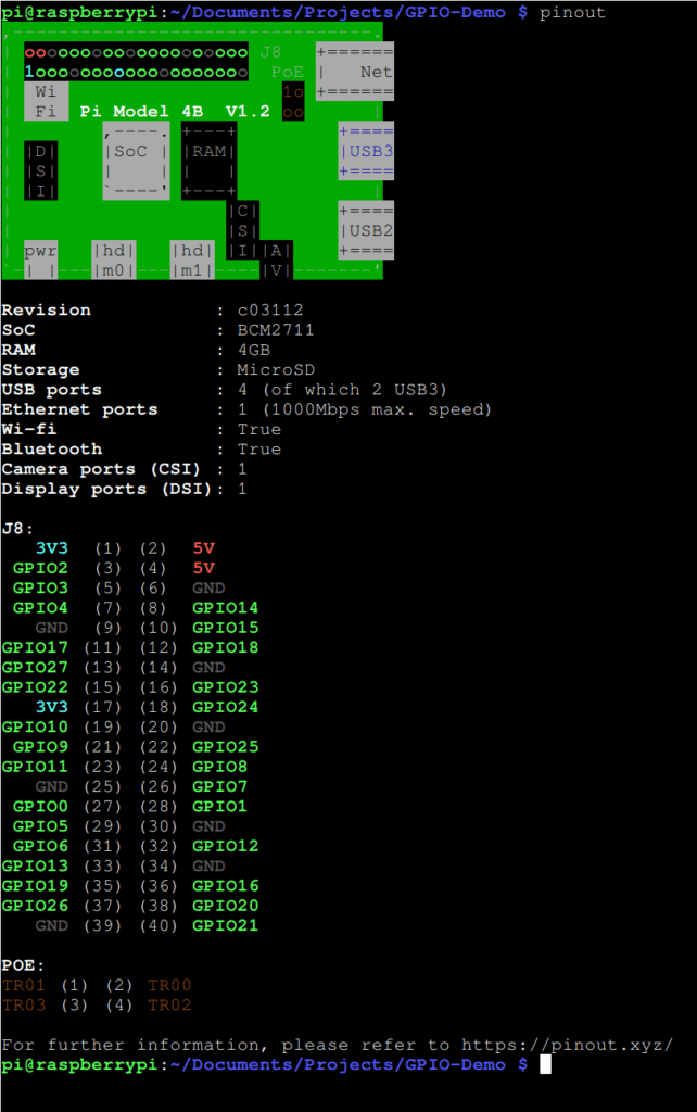
Figure 9 – GPIO Layout of Raspberry Pi 4 Model B
Note, this pinout is strictly for the Raspberry Pi 4 Model B. The pinout for your device may differ. Always check before connecting anything because connecting a wire to the wrong pin may damage the Pi or whatever is connected.
Using Python and the Raspberry Pi
Now that we have a clear idea of the electronic components required for this project, we can begin to examine the Python code and libraries we will be using to obtain basic electronic control of our Raspberry Pi and connected devices. We will begin that examination in part two of this embedded programming tutorial series: Using Python for Basic Raspberry Pi Electronic Controls.
